知识拓展
两台三层交换机可实现不同部门之间的网络互访。所需设备:
(1)DCRS-5650 交换机 2 台。
(2)PC 4 台。
(3)Console 线 1 条。
(4)直通线 5 条。
两台三层交换机 VLAN 路由拓扑结构如图 2-2-11 所示。
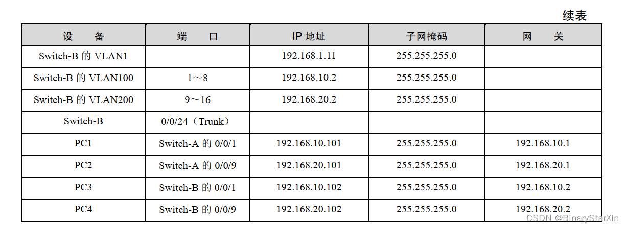
交换机的 VLAN 划分和 PC 的 IP 地址网络参数设置见表 2-2-4。

步骤 1:按照图 2-2-11 连接网络拓扑结构。
步骤 2:按照表 2-2-4 配置计算机的 IP 地址、子网掩码和网关。
步骤 3:将交换机恢复出厂设置。
switch#set default !恢复出厂设置
switch#write !保存配置
switch#reload !重启交换机
步骤 4:为交换机 A 设置主机名称和管理 IP 地址。
Switch(config)#hostname Switch-A !交换机命名为Switch-A
Switch-A(config)#interface vlan 1 !进入VLAN1的接口
Switch-A(Config-if-Vlan1)#ip address 192.168.1.1 255.25.255.0
!配置VLAN1的IP地址
Switch-A(Config-if-Vlan1)#no shutdown !开启该端口
Switch-A(Config-if-Vlan1)#exit
步骤 5:为交换机 B 设置主机名称和管理 IP 地址。
Switch(config)#hostname Switch-B !交换机命名为Switch-B
Switch-B(config)#interface vlan 1 !进入VLAN1的接口
Switch-B(Config-if-Vlan1)#ip address 192.168.1.2 255.25.255.0
!配置VLAN1的IP地址
Switch-B(Config-if-Vlan1)#no shutdown !开启该端口
Switch-B(Config-if-Vlan1)#exit
步骤 6:在交换机 A 上创建 VLAN100 和 VLAN200,并添加相应端口。
Switch-A(config)#vlan 100 !创建VLAN100
Switch-A(Config-Vlan100)#switchport interface e0/0/1-8
Set the port Ethernet0/0/1 access vlan 100 successfully
Set the port Ethernet0/0/2 access vlan 100 successfully
Set the port Ethernet0/0/3 access vlan 100 successfully
Set the port Ethernet0/0/4 access vlan 100 successfully
Set the port Ethernet0/0/5 access vlan 100 successfully
Set the port Ethernet0/0/6 access vlan 100 successfully
Set the port Ethernet0/0/7 access vlan 100 successfully
Set the port Ethernet0/0/8 access vlan 100 successfully
Switch-A(Config-Vlan100)#exit
Switch-A(config)#vlan 200 !创建VLAN200
Switch-A(Config-Vlan200)#switchport interface e0/0/9-16
Set the port Ethernet0/0/9 access vlan 200 successfully
Set the port Ethernet0/0/10 access vlan 200 successfully
Set the port Ethernet0/0/11 access vlan 200 successfully
Set the port Ethernet0/0/12 access vlan 200 successfully
Set the port Ethernet0/0/13 access vlan 200 successfully
Set the port Ethernet0/0/14 access vlan 200 successfully
Set the port Ethernet0/0/15 access vlan 200 successfully
Set the port Ethernet0/0/16 access vlan 200 successfully
Switch-A(Config-Vlan200)#exit
Switch-A(config)#
步骤 7:在交换机 B 上创建 VLAN100 和 VLAN200,并添加相应端口。
Switch-B(config)#vlan 100 !创建VLAN100
Switch-B(Config-Vlan100)#switchport interface e0/0/1-8
Set the port Ethernet0/0/1 access vlan 100 successfully
Set the port Ethernet0/0/2 access vlan 100 successfully
Set the port Ethernet0/0/3 access vlan 100 successfully
Set the port Ethernet0/0/4 access vlan 100 successfully
Set the port Ethernet0/0/5 access vlan 100 successfully
Set the port Ethernet0/0/6 access vlan 100 successfully
Set the port Ethernet0/0/7 access vlan 100 successfully
Set the port Ethernet0/0/8 access vlan 100 successfully
Switch-B(Config-Vlan100)#exit
Switch-B(config)#vlan 200 !创建VLAN200
Switch-B(Config-Vlan200)#switchport interface e0/0/9-16
Set the port Ethernet0/0/9 access vlan 200 successfully
Set the port Ethernet0/0/10 access vlan 200 successfully
Set the port Ethernet0/0/11 access vlan 200 successfully
Set the port Ethernet0/0/12 access vlan 200 successfully
Set the port Ethernet0/0/13 access vlan 200 successfully
Set the port Ethernet0/0/14 access vlan 200 successfully
Set the port Ethernet0/0/15 access vlan 200 successfully
Set the port Ethernet0/0/16 access vlan 200 successfully
Switch-B(Config-Vlan200)#exit
Switch-B(config)#
步骤 8:在交换机 A 上配置 Trunk 端口。
Switch-A(config)#int e0/0/24 !进入端口24
Switch-A(Config-If-Ethernet0/0/24)#switchport mode trunk
!将该端口设置成Trunk模式
Set the port Ethernet0/0/24 mode TRUNK successfully
Switch-A(Config-If-Ethernet0/0/24)#switchport trunk allowed vlan all
set the port Ethernet0/0/24 allowed vlan successfully
Switch-A(Config-If-Ethernet0/0/24)#
Switch-A(Config-If-Ethernet0/0/24)#exit
步骤 9:在交换机 B 上配置 Trunk 端口。
Switch-B(config)#int e0/0/24 !进入端口24
Switch-B(Config-If-Ethernet0/0/24)#switchport mode trunk
!将该端口设置成Trunk模式
Set the port Ethernet0/0/24 mode TRUNK successfully
Switch-B(Config-If-Ethernet0/0/24)#switchport trunk allowed vlan all
set the port Ethernet0/0/24 allowed vlan successfully
Switch-B(Config-If-Ethernet0/0/24)#
Switch-B(Config-If-Ethernet0/0/24)#exit
步骤 10:在交换机 A 上查看 VLAN 的配置。
Switch-A#show vlan
VLAN Name Type Media Ports
---- ------------ ---------- --------- -----------------------------------
1 default Static ENET Ethernet0/0/17 Ethernet0/0/18
Ethernet0/0/19 Ethernet0/0/20
Ethernet0/0/21 Ethernet0/0/22
Ethernet0/0/23 Ethernet0/0/24(T)
Ethernet0/0/25 Ethernet0/0/26
Ethernet0/0/27 Ethernet0/0/28
100 VLAN0100 Static ENET Ethernet0/0/1 Ethernet0/0/2
Ethernet0/0/3 Ethernet0/0/4
Ethernet0/0/5 Ethernet0/0/6
Ethernet0/0/7 Ethernet0/0/8
Ethernet0/0/24(T)
200 VLAN0200 Static ENET Ethernet0/0/9 Ethernet0/0/10
Ethernet0/0/11 Ethernet0/0/12
Ethernet0/0/13 Ethernet0/0/14
Ethernet0/0/15 Ethernet0/0/16
Ethernet0/0/24(T)
Switch-A#
步骤 11:在交换机 B 上验证其配置。
Switch-B#show vlan
VLAN Name Type Media Ports
---- ----------- --------- --------- --------------------------------------
1 default Static ENET Ethernet0/0/17 Ethernet0/0/18
Ethernet0/0/19 Ethernet0/0/20
Ethernet0/0/21 Ethernet0/0/22
Ethernet0/0/23 Ethernet0/0/24(T)
Ethernet0/0/25 Ethernet0/0/26
Ethernet0/0/27 Ethernet0/0/28
100 VLAN0100 Static ENET Ethernet0/0/1 Ethernet0/0/2
Ethernet0/0/3 Ethernet0/0/4
Ethernet0/0/5 Ethernet0/0/6
Ethernet0/0/7 Ethernet0/0/8
Ethernet0/0/24(T)
200 VLAN0200 Static ENET Ethernet0/0/9 Ethernet0/0/10
Ethernet0/0/11 Ethernet0/0/12
Ethernet0/0/13 Ethernet0/0/14
Ethernet0/0/15 Ethernet0/0/16
Ethernet0/0/24(T)
Switch-B#
步骤 12:在交换机 A 上添加 VLAN 的地址。
Switch-A(config)#interface vlan 100 !进入VLAN100的接口
Switch-A(Config-if-Vlan100)#ip address 192.168.10.1 255.255.255.0
!配置VLAN100的IP地址
Switch-A(Config-if-Vlan100)#no shutdown !开启该端口
Switch-A(Config-if-Vlan100)#exit
Switch-A(config)#interface vlan 200 !进入VLAN200的接口
Switch-A(Config-if-Vlan200)#ip address 192.168.20.1 255.255.255.0
!配置VLAN200的IP地址
Switch-A(Config-if-Vlan200)#no shutdown !开启该端口
Switch-A(Config-if-Vlan200)#exit
步骤 13:查看交换机 A 上的 VLAN 地址。
Switch-A#show ip int brief
Index Interface IP-Address Status Protocol
2002 Loopback 127.0.0.1 up up
2004 Vlan1 192.168.1.1 up up
2005 Vlan100 192.168.10.1 up up
2006 Vlan200 192.168.20.1 up up
Switch-A#
步骤 14:在交换机 B 上添加 VLAN 的地址。
Switch-B(config)#interface vlan 100 !进入VLAN100的接口
Switch-B(Config-if-Vlan100)#ip address 192.168.10.2 255.255.255.0
!配置VLAN100的IP地址
Switch-B(Config-if-Vlan100)#no shutdown !开启该端口
Switch-B(Config-if-Vlan100)#exit
Switch-B(config)#interface vlan 200 !进入VLAN200的接口
Switch-B(Config-if-Vlan200)#ip address 192.168.20.2 255.255.255.0
!配置VLAN200的IP地址
Switch-B(Config-if-Vlan200)#no shutdown !开启该端口
Switch-B(Config-if-Vlan200)#exit
步骤 15:查看交换机 B 上的 VLAN 地址。
Switch-B#show ip int brief
Index Interface IP-Address Status Protocol
2002 Loopback 127.0.0.1 up up
2004 Vlan1 192.168.1.11 up up
2005 Vlan100 192.168.10.2 up up
2006 Vlan200 192.168.20.2 up up
Switch-B#
步骤 16:查看交换机 A 的路由表。
Switch-A#show ip route
Codes: K - kernel, C - connected, S - static, R - RIP, B - BGP
O - OSPF, IA - OSPF inter area
N1 - OSPF NSSA external type 1, N2 - OSPF NSSA external type 2
E1 - OSPF external type 1, E2 - OSPF external type 2
i - IS-IS, L1 - IS-IS level-1, L2 - IS-IS level-2, ia - IS-IS inter area
* - candidate default
C 127.0.0.0/8 is directly connected, Loopback
C 192.168.1.0/24 is directly connected, Vlan1
C 192.168.10.0/24 is directly connected, Vlan100
C 192.168.20.0/24 is directly connected, Vlan200
Total routes are : 4 item(s)
Switch-A#
步骤 17:查看交换机 B 的路由表。
Switch-B#show ip route
Codes: K - kernel, C - connected, S - static, R - RIP, B - BGP
O - OSPF, IA - OSPF inter area
N1 - OSPF NSSA external type 1, N2 - OSPF NSSA external type 2
E1 - OSPF external type 1, E2 - OSPF external type 2
i - IS-IS, L1 - IS-IS level-1, L2 - IS-IS level-2, ia - IS-IS inter area
* - candidate default
C 127.0.0.0/8 is directly connected, Loopback
C 192.168.1.0/24 is directly connected, Vlan1
C 192.168.10.0/24 is directly connected, Vlan100
C 192.168.20.0/24 is directly connected, Vlan200
Total routes are : 4 item(s)
Switch-B#
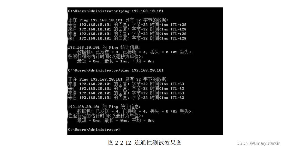
步骤 18:测试网络的连通性。
在 PC3 上 ping PC1 的 IP 地址 192.168.10.101 和 PC2 的 IP 地址 192.168.20.101,网络是连通的,表明利用 SVI 可以实现 VLAN 间的路由,如图 2-2-12 所示。
学习小结
本学习活动介绍了利用 SVI 实现 VLAN 之间的通信,在二层交换机上配置 VLAN 后,只能实现相同 VLAN 的通信,如果想实现 VLAN 间的通信,就必须借助于三层设备(三层交换机或路由器),路由器实现 VLAN 间通信,在后面章节中进行介绍。
版权说明:如非注明,本站文章均为 扬州驻场服务-网络设备调试-监控维修-南京泽同信息科技有限公司 原创,转载请注明出处和附带本文链接。
请在这里放置你的在线分享代码